
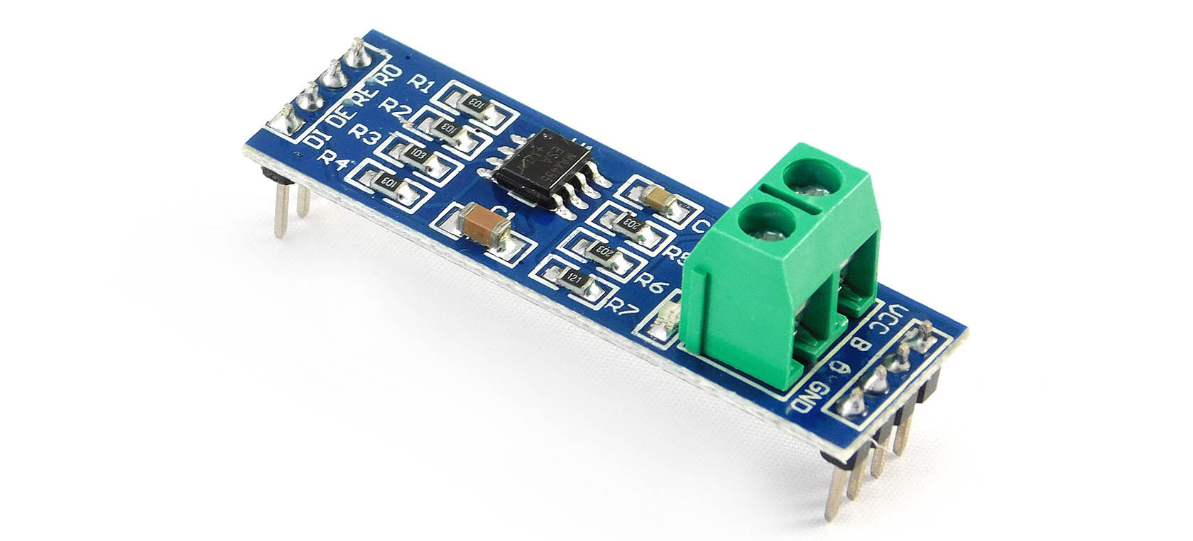
MAX485 TTL to RS485 Converter Module

| Pin Number | Pin Name | Function |
|---|---|---|
| 1 | VCC | Power supply input (5V) |
| 2 | GND | Ground |
| 3 | DI/TX | Data input (TTL level) / Transmit data (RS485 level) |
| 4 | RO/RX | Data output (TTL level) / Receive data (RS485 level) |
| 5 | DE | Data enable (active low) |
| 6 | RE | Receiver enable (active low) |
| 7 | A | RS485 differential signal A |
| 8 | B | RS485 differential signal B |
Multi-Drop Support for Multiple Devices
RS-485 serial connection allows you to connect multiple devices (up to 32) to one communication line generally referred to as ‘multi-drop’.

The devices are usually configured in a Master / Slave mode with a Master device and more than one Slave device. Because they are on the same bus, to avoid any possible conflict, generally, the Slave devices only talk when they are asked for some help from the Master such as requesting a temperature reading.
Interfacing MAX485 MODBUS Serial Communication With Arduino

Example code – MAX485 MODBUS Serial Communication With Arduino
Code for Transmitter
|
1
2
3
4
5
6
7
8
9
10
11
12
|
#include <SoftwareSerial.h>
SoftwareSerial mySerial(3,2);
void setup() {
mySerial.begin (9600);
Serial.begin(9600);
}
void loop() {
mySerial.println (“DIY Hardware Lab !”);
Serial.println (“Hello!”);
delay(1000);
}
|
Code for Reciever
|
1
2
3
4
5
6
7
8
9
10
11
12
13
|
#include <SoftwareSerial.h>
SoftwareSerial mySerial(3,2);
void setup() {
Serial.begin(9600);
mySerial.begin(9600);
}
void loop() {
while(mySerial.available() > 0){
char c = mySerial.read();
Serial.write(c);
}
}
|
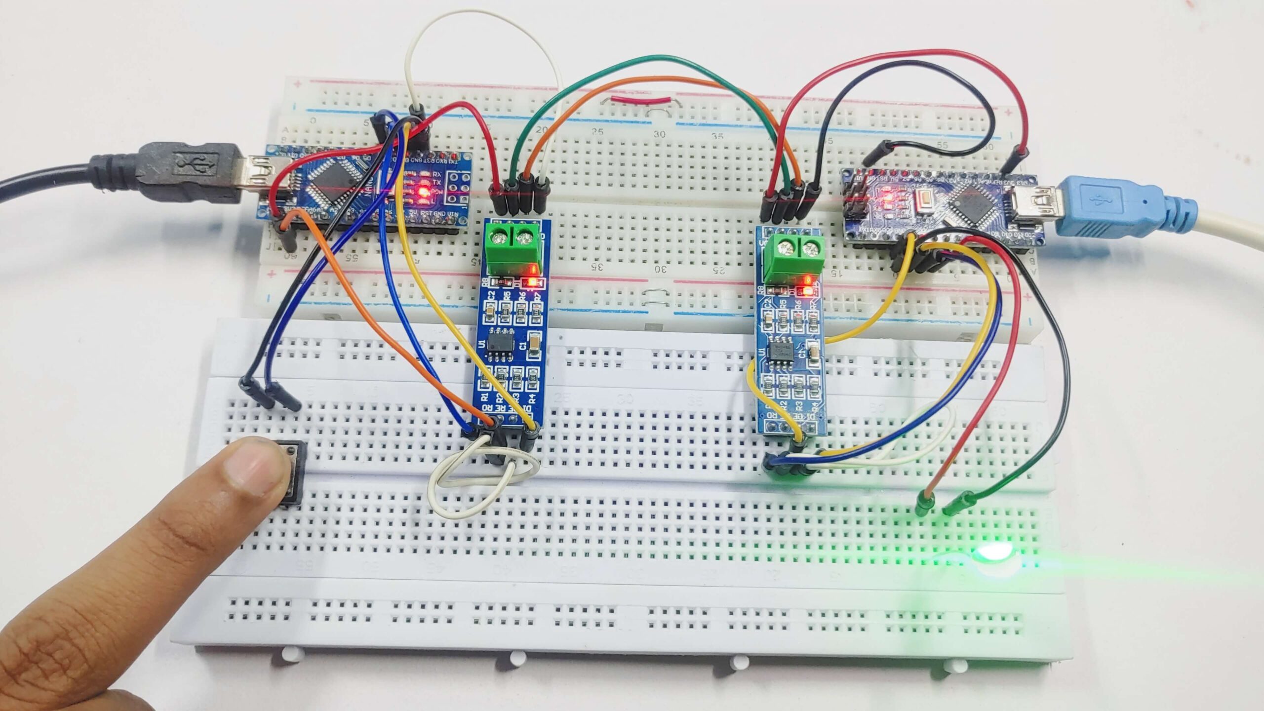
Control LED Using Push Button With MAX485 MODBUS Serial Communication & Arduino

Wiring between RS-485 and Arduino Nano (Master)
| RS-485 Pin | Arduino Nano |
|---|---|
| DI (Data In) | 2 |
| DE (Data Enable) | 5V |
| RE (Receiver Enable) | 5V |
| RO (Data Out) | 3 |
| VCC | 5V |
| GND | GND |
| A | To A of Slave RS-485 |
| B | To B of Slave RS-485 |
Push Button to Arduino
| switch | Arduino Nano |
|---|---|
| Button Pin | 4 |
Wiring between RS-485 and Arduino Nano (Slave)
| RS-485 Pin | Arduino Nano |
|---|---|
| DI (Data In) | 2 |
| DE (Data Enable) | GND |
| RE (Receiver Enable) | GND |
| RO (Data Out) | 3 |
| VCC | 5V |
| GND | GND |
| A | To A of Slave RS-485 |
| B | To B of Slave RS-485 |
LED To Arduino
| LED | Arduino Nano |
|---|---|
| Positive Terminal | 4 |
| Negative Terminal | GND |

Source Code – MAX485 MODBUS Serial Communication With Arduino
Master RS-485 Device Software
|
1
2
3
4
5
6
7
8
9
10
11
12
13
14
15
16
17
18
|
#include <SoftwareSerial.h>
SoftwareSerial mySerial(3, 2); // RX, TX pins for the wireless module
int buttonPin = 4; // button connected to pin 4
void setup() {
mySerial.begin(9600);
pinMode(buttonPin, INPUT_PULLUP); // set pin 4 as input with internal pull-up resistor
}
void loop() {
if (digitalRead(buttonPin) == LOW) { // if the button is pressed
mySerial.write(‘1’); // send ‘1’ character to turn on the LED
} else {
mySerial.write(‘0’); // send ‘0’ character to turn off the LED
}
delay(100); // add a small delay to debounce the button
}
|
Slave RS-485 Device Software
|
1
2
3
4
5
6
7
8
9
10
11
12
13
14
15
16
17
18
19
20
21
22
|
#include <SoftwareSerial.h>
SoftwareSerial mySerial(3, 2);
int ledPin = 4; // LED connected to pin 4
void setup() {
Serial.begin(9600);
mySerial.begin(9600);
pinMode(ledPin, OUTPUT); // set pin 4 as output
}
void loop() {
while (mySerial.available() > 0) {
char c = mySerial.read();
Serial.write(c);
if (c == ‘1’) { // if the received character is ‘1’, turn on the LED
digitalWrite(ledPin, HIGH);
} else if (c == ‘0’) { // if the received character is ‘0’, turn off the LED
digitalWrite(ledPin, LOW);
}
}
}
|
Working
Other Arduino tutorials, you may like to read: